The DM16E1 Series II e DM4E1 Series II family presents PDH multiplexers in conformity with G.751 and G.742 standards. They are Physically comprised of a basic unit for 19” 1.5U-high rack assembly and multiplexes E1 channels, Ethernet, V.11 and E3 in optical or electrical 34M beams.
Point to Point Topology
The equipment leaves the factory configured for this topology, not requiring any type of configuration is used only when the tax E1 (G.703). The aggregate 1 will be considered as the main link and a link aggregate 2 backup, automatic backup.

Point to Point Topology
On the Inverse Multiplexing mode, Bridge port is able to split the data received E1 channels.

Inverse Multiplexing Topology
When in Inverse Multiplexing, some E1’s go through different paths (eg SDH or satellite). Thus the DM16E1 Series II and Series II DM4E1 implement greater tolerance for differences in clocks between the E1 tributaries and also for aggregate E3.
Point to Point Bridge 100M Topology
Functions as an optical multiplexer that operates at a rate of 155Mbit/s (when using the proprietary protocol). The Bridge interface may use a dedicated channel of up to 100Mbit/s (when using the proprietary protocol). It is made available up to 16 TDM channels for communication (G.703, V.11 or Router for a dedicated management). Still, you can use both interfaces for optical aggregate to ensure redundancy (Operation Main and Backup).

Point to Point Bridge 100M Topology
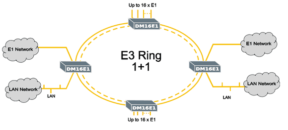
Ring Topology
The cross and regular rings are built bidirectionally (east ring, west ring) like SDH systems: one ring is used for main data link and the other is reserved for use in case of failure. It can be choused any type of aggregate connection between two adjacent equipments in ring (electrical or singlemode/multimode optical). In the cross ring is needed to install two aggregate cards in each equipment. Besides this topology has the advantage of allow the use of single fiber connections in the ring; single fiber optical installation is cheaper and easy. In this topology the aggregate cards may be swapped without breaking the data link. The regular ring may operate with one or two aggregate cards in each equipment. Even if backup is used in this topology the data link is lost in absence of main link aggregate.

Ring Topology
Line Topology
This topology works like a broken cross ring: all line network equipments use two aggregate cards and the line terminal equipments use one aggregate card. Line topology don’t have backup and the entire link is lost if a single aggregate connection is down.

Line Topology
Regenerator Topology
In this topology the equipment act as an optical regenerator, without extract or add any tributary data in the aggregate.

Regenerator Topology
Optical Modem and Interface Converter Topology
The Interface converter is used to convert E3 framed/unframed interfaces. If backup protection is needed in optical side it can be done using the optical modem topologies. In this case both aggregates use optical cards while the electrical E3 G.703 interface is provided by an additional internal E3 card (DM16E1 Series II-E3Ei), positioned in the Ethernet bridge position. The internal electrical E3 interface uses tributary 01 connection. Transparent Optical Modem topology offers interoperability with another supplier’s equipment in E3 electrical interface allowing unframed E3 rate operation; regenerator and transparent interface converters features optical compatibility too.
As topologias modem ótico transparente, regenerador e conversor de interface transparente permitem interoperabilidade com interfaces ópticas a 34Mbit/s de outros fabricantes com ou sem a estrutura de frame.

Conversor Topology

Conversor Topology with Protection
Ring Optical Modem
Ring optical modem topologies can receive external E3 electrical data to be distributed along the ring. It allows framed electrical E3 (containing framed E2) signals from any source.

Ring Optical Modem Topology