Knowledge in one place.
Applications Engineering - Adriano Guedes
This article analyzes a typical scenario with Multi Chassis Link Aggregation (MC-LAG) and demonstrates how the planned architecture can maximize resilience in an MC-LAG deployment scenario in an existing L2 network, including mitigating split-brain scenarios.
The phenomenon known as split-brain occurs when two or more nodes in a system that should operate together lose communication with each other, but remain active independently, each believing the other node is down. It is as if the two devices that should operate in active/passive mode act as active, directly impacting the scalability of the topology, generating instability and loss of connectivity.
Traditionally, link aggregation, where several physical interfaces behave as a logical interface, always operates from device A to device B, distributing traffic according to its variability, among the available interfaces, as seen in the image below.
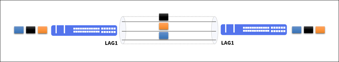
Balancing can occur using criteria such as:
There is no better or worse method, but rather one that adapts to the characteristics of your topology.
MC-LAG, on the other hand, brings the idea of aggregating physical links into a logical one, but with the possibility of it being established with different destinations, as shown below.
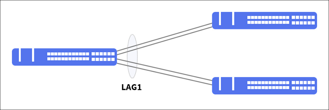
This makes it an excellent solution for providing redundancy, resilience, and load balancing in critical environments.
On devices with the DmOS operating system, MC-LAG operates in Active/Standby mode, where one PE device assumes the active role and the other the standby role, serving as a backup device. Traffic will be forwarded only to the PE device marked as active.
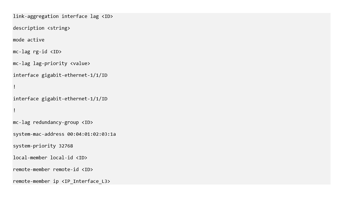
Configuration between PE devices involves the following parameters:
For MC-LAG to operate, we will need:
The lowest lag-priority setting will determine which physical connection (of the two allocated for link aggregation) in the LAG will be used by traffic, called active, and which will be on standby. Using the same lag-priority value on both PEs should be avoided.
MC-LAG pairs use the Inter-Chassis Control Protocol (ICCP) to exchange control information and coordinate with each other, ensuring that data traffic is routed correctly.
LACP is used to discover multiple links from a CE device connected to an MC-LAG pair and must be configured on both MC-LAG pairs for proper operation.
The LAG admin-key parameter between the PEs must be the same; DmOS uses the same LAG ID value as the admin-key.
Below we have a typical MC-LAG scenario, with perfect operating conditions between all equipment. We emphasize that the topology is composed of CE A – identified by the image of a computer and switches PE A and PE B.
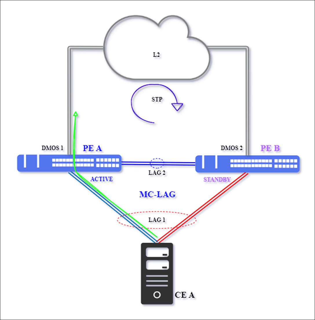
Traditional MC-LAG Scenario
The data flow will be routed through the active LAG 1 interconnection, indicated by the green arrow, between PE A and CE A, and then through the main uplink interface with the L2 network above the two switches configured in MC-LAG. PE B will be kept in standby status and without data traffic between PE B and CE A.
The L2 network, identified by the cloud in the image above, will have protocols to prevent logical loops, such as spanning-tree (xSTP), EAPS, ERPS, or others. Therefore, the port through which the traffic will be routed, in our case, PE A – DmOS 1, must be active/open.
In normal network operation, links are subject to simple and more complex failures, which we detail below, which generate five distinct behaviors.
Case 1 – Single Failure between CE and PE
The failure, marked with a red "X" in the topology below, occurs in one of the physical connections that make up LAG1 and operates as the primary interconnection link between PE A and CE A.
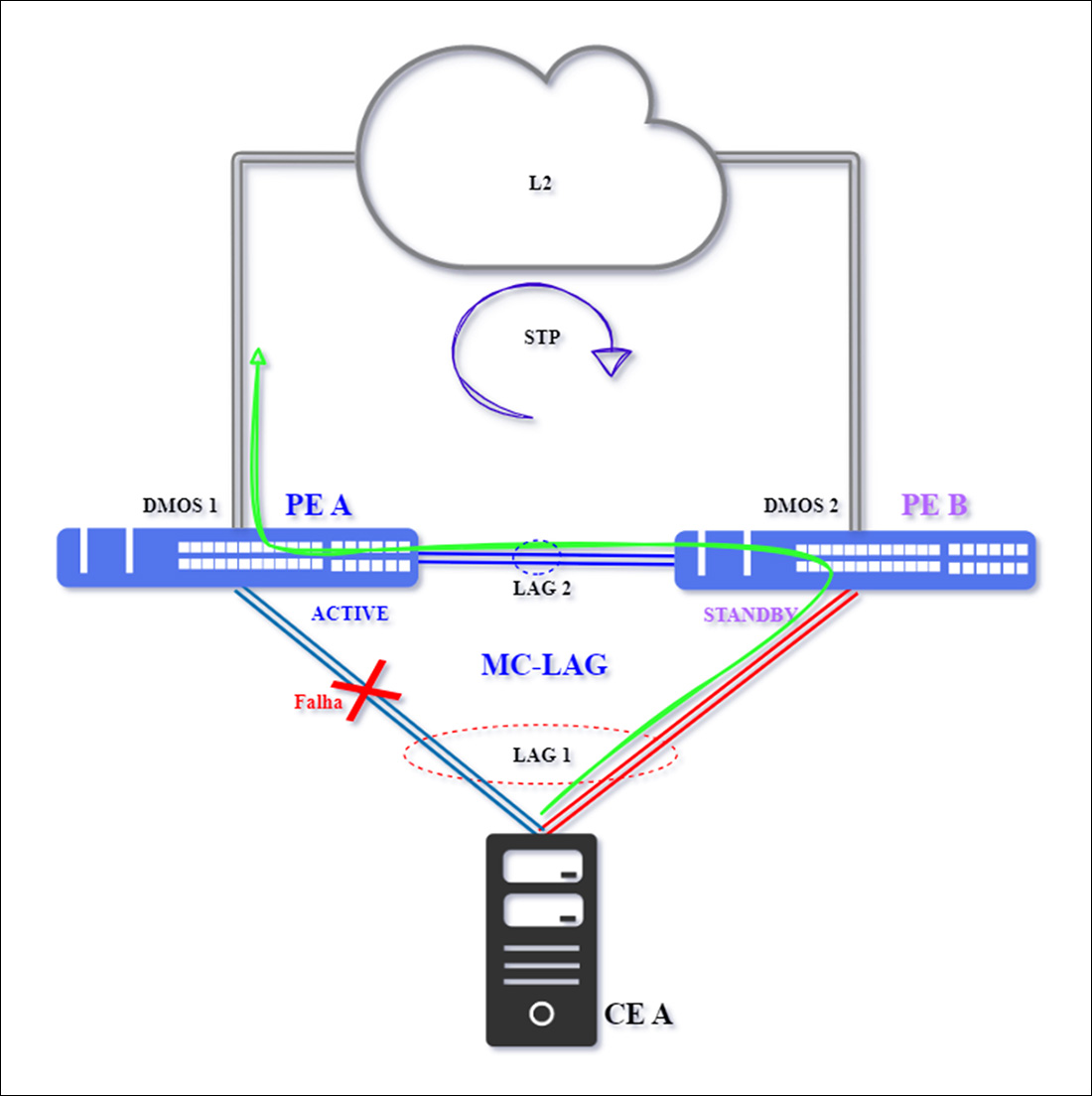
Note that PE A – DmOS 1 remains active, as there was no loss of communication with PE B – DmOS 2. Therefore, traffic will flow through the other member of LAG1, the connection between CE A and PE B. Traffic forwarding to the L2 network will continue through PE A, as it travels through the interconnection between the two switches (A and B) in MC-LAG.
Normalization will occur after the primary interconnection between PE A and CE A becomes available.
Case 2 – Single Failure between PEs
The failure occurs in the interconnection link between the PEs, which is where the split-brain situation occurs.
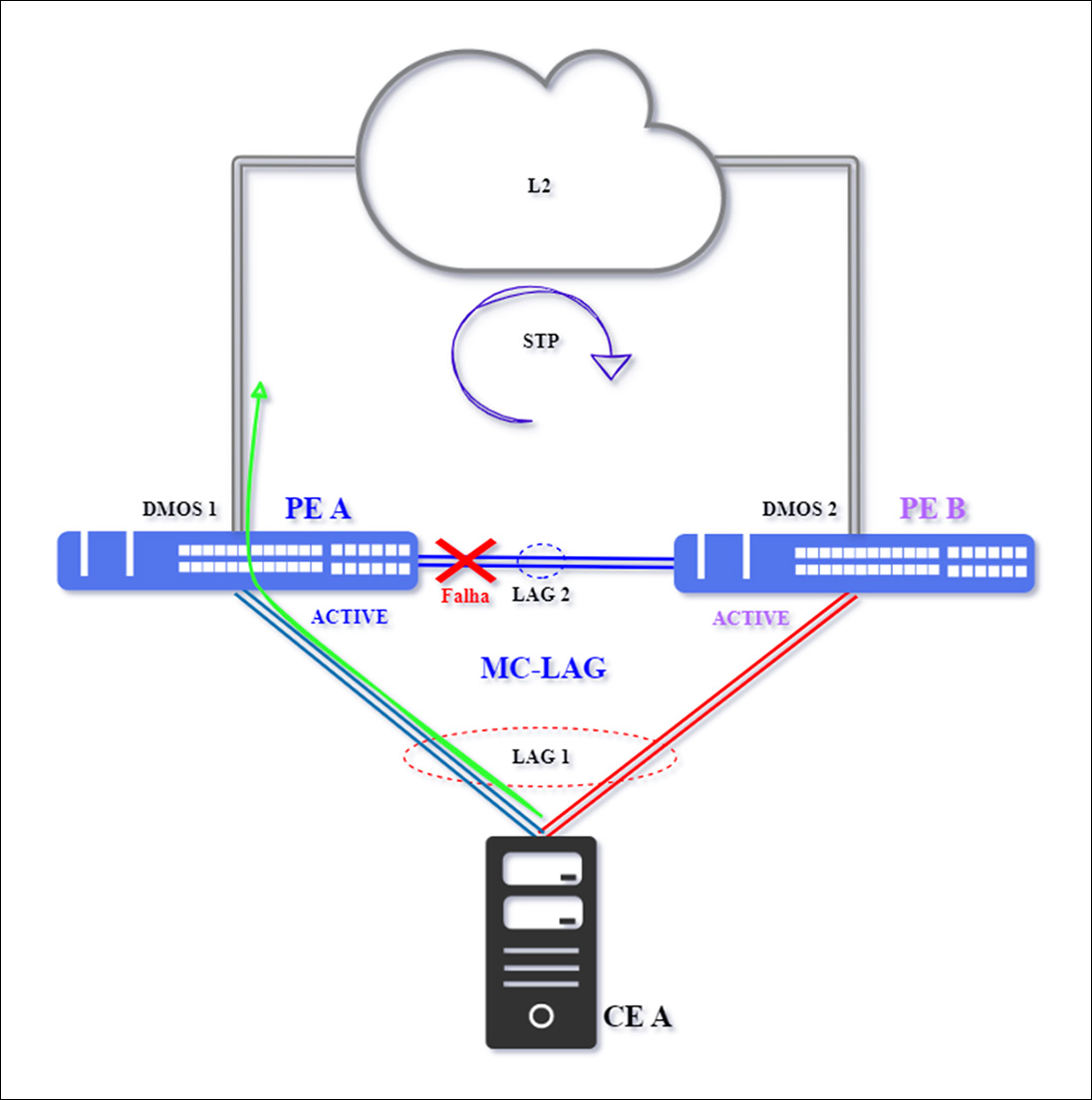
In the above scenario, a split-brain condition will theoretically occur. Communication between PEs is interrupted, causing PE A to remain in the Active state, but PE B's status will change to Active.
In practice, MC-LAG traffic will continue to flow undisturbed; traffic will not converge to PE B. However, it is important that the connection between PEs be reestablished, as this is a key focus in the MC-LAG architecture.
The System Priority value defines the device's preference for selecting active links in a LAG. This value is transmitted in LACPDUs, allowing the remote device (CE) to correctly interpret the priority hierarchy between systems.
To restore operation, the control link between PEs must be restored, allowing PE B to return to the Standby state, while maintaining PE A as the only Active link.
Case 3 – Single Failure on Active PE
The failure occurs on PE A, which operates as active MC-LAG equipment, interrupting the main interconnection link between PE A and CE A, as well as the interconnection between PEs.
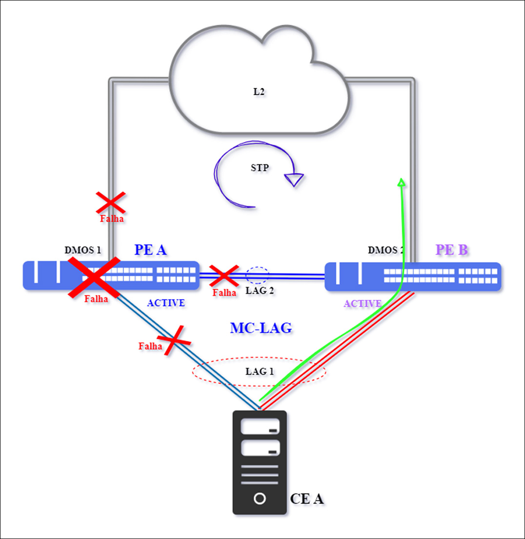
Note that this scenario represents both the total failure of PE A to and the simultaneous interruption of the 03 connections (total insulation) that connect it to topology.
The PE A equipment will be totally inoperative, as a result, PE B and CE A Lose communication with active equipment, making the PE B assume the role of active, here does not happen Split Brain, because only PE B will assume as active.
Traffic will be redirected to the secondary LAG 1 connection between PE B and CE A - Green arrow. As for interconnection with the L2 network, since PE A is totally inoperative, the interface will be identified as Down, causing the resilience protocol to converge.
Topology will be re -established after the PE A equipment and its connections are normalized.
Case 4 – Double Fault on Active PE
The isolation of PE A (active MC-LAG equipment) can occur due to a double fault, when the interconnection link between PE A and CE A and the interconnection between PEs are inactive, such as due to a break.
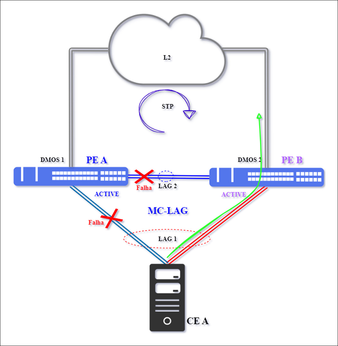
With this failure, the PE A and PE B equipment lose communication and both become Active, causing the phenomenon known as split brain. However, even with both PEs assuming Active status, there will be no impact, as there is a failure in the main connectivity of LAG 1 between PE A and CE A, indicated by the red “X”. Traffic will be redirected to the secondary interconnection between CE A and PE B.
It is important to note that the interconnection with the L2 network (cloud) is outside the MC-LAG context. Communication continuity will depend on the resiliency protocol used in the network, which must detect that PE A is no longer a valid and active path to CE A, thus converging traffic to the connection with PE B.
To reestablish the topology, first activate the interconnection between PE A and PE B, so that only PE A remains in the Active status. Then, ensure that the interconnection between PE A and CE A is restored.
Case 5 – Double Failure on the CE
This occurs when the CE is isolated due to a double failure in the primary and secondary links of LAG 1, those used for interconnection with the PEs.
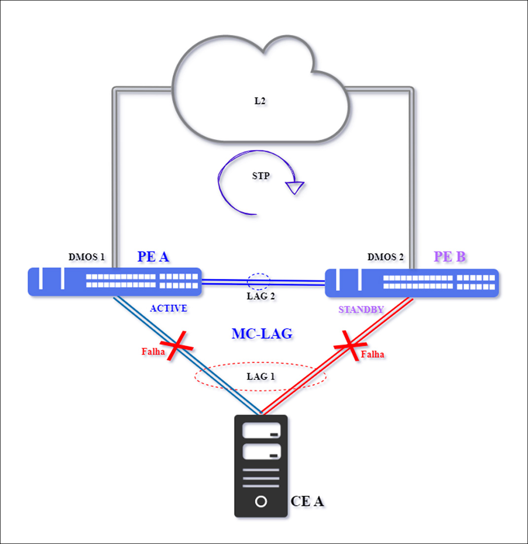
This failure is uncommon, but it causes complete traffic interruption.
PE A will remain in Active status, and PE B in Standby status, as communication between PEs remains operational. This represents the realization of the risk of having a single CE.
Traffic will be reestablished after CE A returns to normal.
Conclusion
DmOS adopts a simplified approach to Cisco vPC, eliminating the need for parallel control channels (Peer-Link and Keepalive), which reduces infrastructure and configuration complexity and costs without compromising resiliency. The Cisco vPC solution is illustrated in this external documentation: 🔗 vPC Failure Scenarios – Impact and Solution
We recommend reading the MC-LAG topic of our DmOS quick configuration guide, where we highlight the application of different priorities in the system priority and mc-lag lag-priority fields.
This practice is essential to avoid traffic impacts in the event of a MC-LAG control session (ICCP) loss, as shown in Case 2.
The MC-LAG feature stands out for its service delivery and high availability between switches, preventing complete interruption of customer traffic. It is present in datacenters, Internet service providers, and corporate environments.
The potential failures mentioned are intended to alert the possibility of split-brain, which could compromise network integrity. However, with tips and planning, mitigation of problems becomes more effective.
The System Priority parameter is included in the LACPDUs (Link Aggregation Control Protocol Data Units) exchanged during LACP establishment between the PE devices and the CE device.
A system's unique identification (System ID) is composed of the concatenation of a unique administered MAC address and the configured System Priority. In other words, the system priority directly influences which side will be elected as the primary system in the LAG.
In short, the device with the lowest System Priority value will be selected as active and will have the primary links in the LAG. This parameter is sent in LACPDU control packets, ensuring that the remote device (CE) correctly identifies and applies the received priorities, provided it implements the IEEE 802.1AX standard.
The MC-LAG solution between PEs was developed for operation between devices from the same manufacturer and does not guarantee interoperability with third parties. However, the device positioned as a CE does, as long as it complies with IEEE 802.1AX, as LACP was designed to interoperate between different manufacturers.
The cases presented illustrate hypothetical failures that are largely mitigable with the best configuration practices discussed in this article.
All configurations are available in our "DmOS – Quick Configuration Guide" and at https://www.datacom.com.br/en/blog/120/mc-lag-no-dmos-alta-disponibilidade-e-escalabilidade-em-infraestruturas-de-rede.
If you have any questions throughout the process, our Datacom Support and Datacom Sales teams are ready to support you every step of the way, ensuring excellence, agility, and continuous growth for your business.
Remember that Datacom has a comprehensive structure at its headquarters where we offer in-person training, as well as an online training platform (DATACOM EAD). During the training, you'll be able to configure various topologies and application scenarios, in addition to receiving guidance from our professionals on a series of best practices that will greatly enhance your network operations.
Also, subscribe to our YouTube channel, sign up to receive notifications, and share the link on your social media.
Back to blog
